
CABLE CLEAT
Introduction

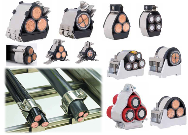 WAC Cable Cleats are designed to support and retain your cables within your cable tray system in everyday conditions. More importantly,
they help prevent damage in short circuit conditions.
Unfortunately, short circuits do happen, and when they do, they are destructive and dangerous. Cable Cleats are one of the first lines of
defense to help protect your personnel, your cables, and your cable tray systems.
Trefoil Cable cleats
Trefoil cable formation is installed where three phases are carried by three single core power cables rather than a single multicore
cable - installing three single core cables using trefoil cleats minimises the induction of eddy currents and maintains current carrying
capacity of the circuit.
Single Core Cables Installed in Trefoil Formation Voltages are induced in the sheath of power cables running in parallel which result in
circulating currents flowing in the cable sheaths. The distances between single core cables running in parallel determine the voltages
induced. With single core cables in trefoil formation (touching each other) the distances between the cables are minimum and thus the
voltages induced are minimised and hence the circulating currents - the circulating currents cause localised heating.
Technical Details of Cleats
1 . TECHNICAL SPECIFICATIONS
A. Cable Cleats and intermediate restraints shall comply with the performance requirements in Article 392.8(d) of NFPA-70-2008,
The National Electrical Code, or C22.1, The Canadian Electrical Code, as applicable.
B. Cable Cleats and intermediate restraints shall be classified, tested and certified according to IEC 61914:2009 Clause 6.4.4, Cable
Cleats for Electrical Installations by an independent third-party testing laboratory, as follows:
1. Classified according to material as
a. Metallic, or
b. Composite
2. Classified according to temperature
a. Maximum temperature for permanent application of +60°C
b. Minimum temperature for permanent application of -40°C
3. Classified according to resistance to impact as ‘Very Heavy’ (i.e. greater than 20J impact energy at 400mm height)
4. Classified by an independent third party testing laboratory in relation to resistance to electromechanical forces as follows:
a. Category 1: (i.e. no failure that will affect the intended function of holding the cables in place), or
b. Category 2: (i.e. cables and cable cleats and intermediate restraints shall be intact and re-usable after sustaining two successive
short circuits and there shall be no cuts or damage to the outer cable sheath, and the cables shall meet the requirements of the
voltage withstand test)
c. The vendor shall also declare
1) The values of IPEAK and ISC-RMS for the aforementioned short circuit classification
2) The arrangement depicting the spacing between the Cable Cleats and intermediate restraints
3) The cable configuration (i.e. trefoil, flat, etc.) utilized to obtain the short circuit classification
4) The spacing between cables in the aforementioned configuration
5) The outside diameter of the cable utilized
5. Classified according to flame application limits where the flame application time must be at least 30 (+0/-1) seconds
6. Marked with the manufacturer’s or responsible vendor’s name, logo or trademark, along with the product identification
Cable Cleat
Terminal Lugs, Cable Glands & Earthing Accessories
2:2 Log on to www.wacaccs.co.uk
Cable Cleat
1.2 SHORT CIRCUIT RATING
A. The maximum mechanical force between conductors during exposure to a short circuit (equation recognized by IEC 61914:2009)
is stated as:
B. The manufacturer will deliver short circuit mechanical force calculations in accordance with IEC 61914:2009 for the following
Where:
= Maximum Force on Conductor (N/m)
= 1st Cycle Peak Asymmetrical Short Circuit Current (kA)
= Cable outside diameter (m)
2 . MATERIAL AND CONSTRUCTION
A. The use of LSF pads are recommended for Cable Cleats and intermediate restraints where the cable would otherwise be in direct
contact with a metal component to:
1. Cushion cables from the magnetic forces arising during fault currents
2. Protect cables from chafing against the mounting system between two modules subject to the differential movement (common
on offshore structures and marine vessels)
3. Protect the cables from the extreme movement found in high-shock installations (e.g. military and seismic applications), and
4. Restrain cables from axial movement in vertical cable runs or during periods of thermal elongation
B. Each Cable Cleat shall have the capability to accommodate a range of cable outside diameters.
C. Metallic or composite cleats shall be non-magnetic 316L marine grade stainless steel (including brackets, mounting adapters and
any permanently mounted manufacturer supplied installation and fastening means).
D. Pads shall be low-smoke, low-fume, zero halogen, polymeric material with UV stabilization for use in high salt, marine outdoor
(e.g. exposed to sunlight) locations.
E. Each Cable Cleat shall have the capability to accommodate a range of cable outside diameters.
F. Cable Cleats shall have “edge folded” design to protect cable outer sheathing in the event of a short circuit.
G. Cable Cleat edges shall be free of burrs and cracks to ensure cable safety.
H. The manufacturer shall provide test reports and product data sheets detailing the peak and RMS currents to which the cable
cleats have been tested, both for category 1 and category 2 classifications
3 . INSTALLATION
A. Install cable cleats according to manufacturer’s guidelines.
B. Install cable cleats [where recommended by manufacturer] [as indicated on Drawings].
C. Cable cleats should always be installed at the beginning, middle and end of a bend, and at no time should the distance between
cleats on a bend be more than 0.3M center to center.
D. It is not necessary for every cleat to be attached to the tray. Every other cleat must be attached to the tray system to mount cable
in tray. Unattached cleats provide additional restraint to keep cables bundled
E. Cable bend radius should be 8 to 12 times the cable diameter.